- Design Point 0
A periphery of the flange at the web edge or at the fillet start - Design Point 1
A flange at a load application point (this can be checked as wheel spacing in Window 1.4) - Design Point 2
Flange edge
Question
I would like to use the CRANEWAY add-on module to design a suspension crane. Where are design points 0, 1, and 2 for the stress analysis on the bottom flange and for the fatigue design?
Answer:
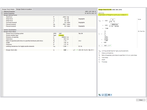
The design points in CRANEWAY have been adopted in compliance with the standard. In this case, the stresses are calculated for the following locations:
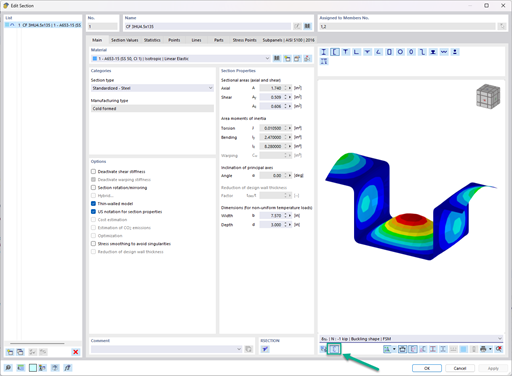
These points are not displayed in the resulting cross-section graphic in the CRANEWAY program. However, there is always a stress point at design points 0 and 2 for which the result values can be displayed directly.
Do you have any questions?
For crane runways with large spans, the horizontal load from skewing is often relevant for the design. This article describes the origin of these forces and the correct input in CRANEWAY. The practical implementation and the theoretical background are discussed.
The three types of moment frames (Ordinary, Intermediate, Special) are available in the Steel Design add-on of RFEM 6. The seismic design result according to AISC 341-22 is categorized into two sections: member requirements and connection requirements.
The Steel Design add-on in RFEM 6 now offers the ability to perform seismic design according to AISC 341-16 and AISC 341-22. Five types of seismic force-resisting systems (SFRS) are currently available.
The three types of moment frames (Ordinary, Intermediate, Special) are available in the Steel Design add-on of RFEM 6. The seismic design result according to AISC 341-16 is categorized into two sections: member requirements and connection requirements.
In the ultimate configuration of the steel joint design, you have the option to modify the limit plastic strain for welds.
The "Base Plate" component allows you to design base plate connections with cast-in anchors. In this case, plates, welds, anchorages, and steel-concrete interaction are analyzed.
In the "Edit Section" dialog box, you can display the buckling shapes of the Finite Strip Method (FSM) as a 3D graphic.
- Design of five types of seismic force-resisting systems (SFRS) includes Special Moment Frame (SMF), Intermediate Moment Frame (IMF), Ordinary Moment Frame (OMF), Ordinary Concentrically Braced Frame (OCBF), and Special Concentrically Braced Frame (SCBF)
- Ductility check of the width-to thickness ratios for webs and flanges
- Calculation of the required strength and stiffness for stability bracing of beams
- Calculation of the maximum spacing for stability bracing of beams
- Calculation of the required strength at hinge locations for stability bracing of beams
- Calculation of the column required strength with the option to neglect all bending moments, shear, and torsion for overstrength limit state
- Design check of column and brace slenderness ratios
Where can I change the steel grade of a crane girder? Although I have set Steel St 37.2 in RSTAB, only S235 is used for the calculation in CRANEWAY.
Recommended Products for You