General
Each nodal support has its own local axis system. The axes are defined with X', Y', and Z'. By default, this support axis system is based on the global axis system of the RFEM or RSTAB file. However, it is also possible to define a user-defined axis system or simply a rotation. In the example shown here, the support axis systems are shown for all nodal supports.
The options of the individual nonlinearities are shown for the displacement inX'. Similar definitions apply for the other two support axis directions.
Note: The nonlinearity always refers to the acting support force.
Failure if Negative PX'

If the acting support force is directed towards the axis X', the support fails in the direction X' and all the other support conditions act linearly.
Failure if Positive PX'

If the support force is positive and thus aligned with the support axis X', the support fails in the direction X' and all the other support conditions act linearly.
Failure All if Negative PX'

If the acting support force is directed towards the axis X', the support fails completely. In this case, no forces or moments are absorbed by this support.
Failure All if Positive PX'

If the support force is positive and thus aligned with support axis X', the support fails completely. In this case, no forces or moments are absorbed by this support.
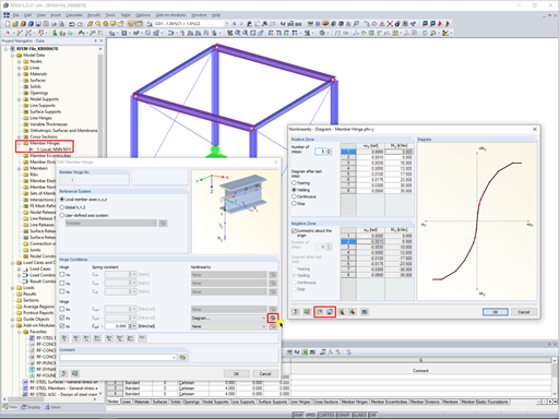
Partial Effect: Slippage

The partial activity is defined in an additional menu. It is possible here to independently define the support for the positive zone (positive support force P-X' and positive displacement uX') as well as the negative zone (negative support force P-X' and negative displacement uX'). The settings are then displayed graphically in a diagram.
If the support has been defined as “fixed” in X', the support node with the defined “complete” and “slippage” support activity is deformed until the defined slippage occurs. Then, the acting support force will be transferred completely. If a spring has been defined, it is effective after reaching the defined slippage.
Partial Effect: Yielding and Slippage

By selecting this option, you can define a limit support force and a value for the slippage. Again, this can be done independently for the positive and the negative zone. If a greater deformation than the defined slippage is reached, the support can only transfer the defined limit support force. If the acting support force exceeds the limit support force, the deformation increases further without increasing the support force.
Partial Effect: Spring and Slippage

If a spring constant has been defined for the support, an additional option, “Fixed from support displacement u+”, is available for “Partial activity”. As already described, it is possible to define a limit value for the slippage. Furthermore, the activity of the defined spring is now limited by the limiting “displacement” value. A linear translational spring operates between the “Slippage” and the “Displacement” limiting values. If the deformation becomes greater than the “Displacement” limiting value, the support force is absorbed completely without further increase of the deformation. As with all other options, this can also be defined separately for the positive and the negative zones.
Partial Effect: Tearing from Support Force

If a spring constant has been defined for the support, “Tearing from support force P+” can also be specified for the support. This option can again be combined with slippage. The support force increases accordingly with regard to the spring constant until the defined limit support force is reached. If the limit support force is exceeded, the support fails suddenly for this direction.
My next article will describe other options that have not been explained here.


.png?mw=350&hash=b023d6c658e181cb7d69028c0f3994dedab96fc5)


.png?mw=512&hash=7193b10f53ed10727f51caee9a094b21a1e153cd)