Answer:
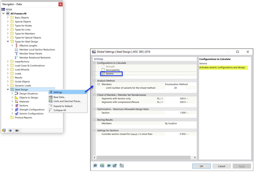
Tapered members must not be designed according to the simplified equivalent member method!For steel structures, the design can be performed by considering the warping torsion or using the General Method. These methods are described in this technical article.
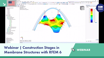
For timber structures, the design can also be performed by considering the warping torsion. The method for timber structures is explained in detail in this webinar.
According to the equivalent member method, the design can be performed if the provisions of the explanations for DIN 1052, Section E8.4.2 (3) for variable cross-sections are met. In various sources of technical literature, this method is adopted for Eurocode 5. An example of this can be found in the document on brettschichtholz.de, page 64 ff.
In the RX‑TIMBER program, the design of tapered members is performed according to the equivalent member method. This is briefly explained in a simple example.
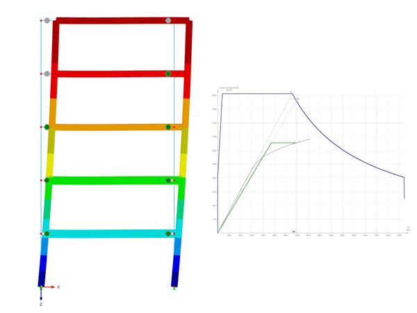
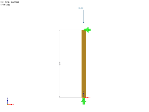
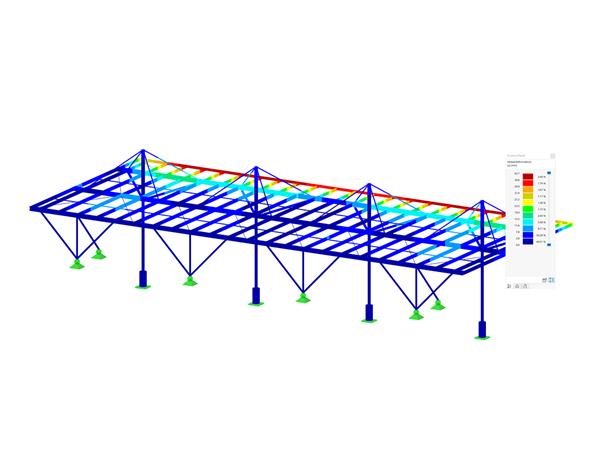
Structural System (Image 01):
- Span length: 8 m
- Beam height right: 80 cm
- Beam height left: 26 cm
- Roof pitch: 3.9°
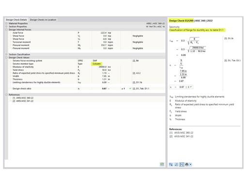
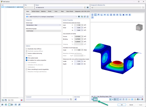
No stiffening is defined. The lateral-torsional stability becomes governing with 99% (Image 02) at the x‑location 1.598 m. The cross-section height is 36.8 cm. However, the slenderness ratio is based on the equivalent cross-section height of 60.9 cm (Image 03).
The equivalent cross-section height results at the x-location 5.2 m about 0.65 × 8 m = 5.2 m.
If the stiffening is in the middle of the span, for example, the equivalent height for the x‑location changes to 45.3 cm.
Since the stiffening is usually applied over the member length, the height must be calculated according to a special algorithm. The supports are always applied as fixed points and the equivalent heights are calculated on the basis of the x-locations of the design checks.
For the example, this results in: x0.65 = 0.32 × 4 m + 1.598 m = 2.878 m


.JPG?mw=350&hash=d57486d45e0440dd9a6be9be91368a3e4f42f4b9)


.jpg?mw=350&hash=91f398b559b26a6ac36fd7ecdf5e395e7b9b856d)


.png?mw=600&hash=49b6a289915d28aa461360f7308b092631b1446e)