Answer:
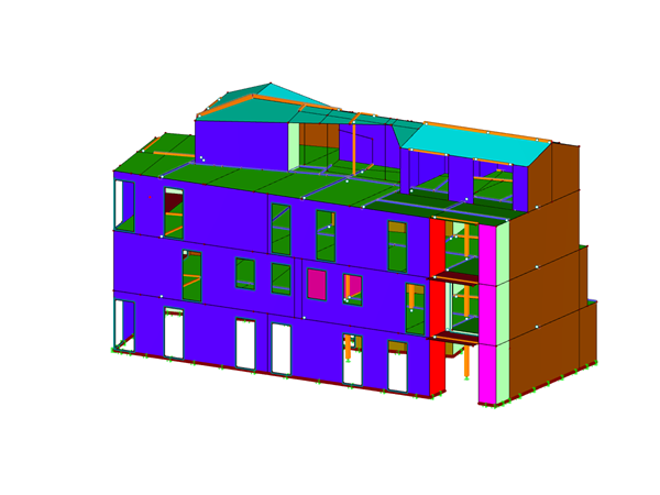
The nonlinear material models are only available in the 3D environment. Please make sure that the model type is set to "3D" (see Image 02).
Question
When creating a material, there are no nonlinear material models available for surfaces or solids. Why?


Do you have any questions?


Length: 00:01:20 min

Length: 00:01:29 min

Length: 00:05:16 min

Length: 00:02:39 min
Length: 00:00:53 min

Length: 01:08:12 min

Length: 00:58:00 min

Length: 00:55:53 min
Length: 01:02:19 min


Utilize the RF-/STEEL Cold-Formed Sections module extension to perform ultimate limit state designs of cold-formed sections according to EN 1993-1-3 and EN 1993-1-5. In addition to the cold-formed cross-sections from the cross-section database, you can design general cross-sections from SHAPE-THIN.

The design of cold-rolled steel products is defined in EN 1993-1-3. Typical cross-section shapes are channel, C, Z, top hat, and sigma sections. These are cold-rolled steel products made of thin-walled sheet metal that has been cold-formed by roll-forming or bending methods. When designing the ultimate limit states, it is also necessary to ensure that local transverse forces do not lead to compression, crippling of the web, or local buckling in the web of the sections. These effects can be caused by local transverse forces by the flange into the web, as well as by support forces at the supported points. Section 6.1.7 of EN 1993-1-3 specifies in detail how to determine the resistance of the web Rw,Rd under local transverse forces.

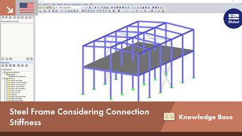
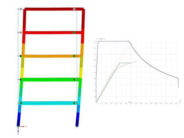
The following example presents a comparison between a shell model and a simple member model performed in RFEM. In the case of the shell model, there is a beam suspended in surfaces, which is modeled with restraints on both sides due to the boundary conditions. This is a statically indeterminate system that forms plastic hinges when overloaded. The comparison is carried out on a member model that has the same boundary conditions as the shell model.

With RF-/STEEL EC3, you can utilize nominal temperature-time curves in RFEM and RSTAB. The standard time-temperature curve (ETK), the external fire curve and the hydrocarbon fire curve are implemented. Moreover, the program provides the option to directly specify the final temperature of steel.


In the ultimate configuration of the steel joint design, you have the option to modify the limit plastic strain for welds.

The "Base Plate" component allows you to design base plate connections with cast-in anchors. In this case, plates, welds, anchorages, and steel-concrete interaction are analyzed.
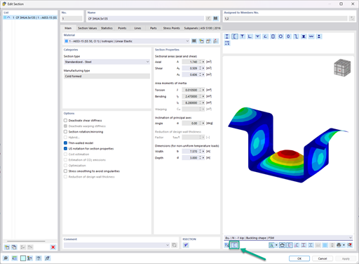
In the "Edit Section" dialog box, you can display the buckling shapes of the Finite Strip Method (FSM) as a 3D graphic.
- Design of five types of seismic force-resisting systems (SFRS) includes Special Moment Frame (SMF), Intermediate Moment Frame (IMF), Ordinary Moment Frame (OMF), Ordinary Concentrically Braced Frame (OCBF), and Special Concentrically Braced Frame (SCBF)
- Ductility check of the width-to thickness ratios for webs and flanges
- Calculation of the required strength and stiffness for stability bracing of beams
- Calculation of the maximum spacing for stability bracing of beams
- Calculation of the required strength at hinge locations for stability bracing of beams
- Calculation of the column required strength with the option to neglect all bending moments, shear, and torsion for overstrength limit state
- Design check of column and brace slenderness ratios
How do I create a frame joint with taper in JOINTS Steel - Rigid?
Is it possible to set a plastic calculation of the internal forces in RSTAB, or are the internal forces exclusively calculated elastically?
The design ratio of the cross-section check is different for the RF‑/STEEL and RF‑/STEEL EC3 add-on modules. What is the reason?
How can I reduce the calculation time for members with a nonlinear material model in RFEM 6 and RSTAB 9?
Why are the stresses of the structural analysis different from those calculated with the Stress-Strain Analysis add-on?
Is it possible to use the general method according to EN 1993‑1‑1, 6.3.4 to design structural components with an asymmetric cross-section in the Steel Design add-on for RFEM 6 or RSTAB 9?

.jpg?mw=350&hash=91f398b559b26a6ac36fd7ecdf5e395e7b9b856d)


Recommended Products for You
RFEM 6 | Main Program RFEM 6

The new generation of 3D FEA software is used for the structural analysis of members, surfaces, and solids.
Price of First License
4,170.00 USD
RFEM 6 | Design

The Concrete Design add-on allows for various design checks according to international standards. You can design members, surfaces, and columns, as well as perform punching and deformation analyses.
Price of First License
2,550.00 USD
RFEM 6 | Additional Analysis

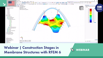
The Construction Stages Analysis (CSA) add-on allows for considering the construction process of structures (member, surface, and solid structures) in RFEM.
Price of First License
1,570.00 USD
RFEM 6 | Additional Analysis

In RFEM, the Geotechnical Analysis add-on uses properties from soil samples to determine the soil body to be analyzed. The accurate determination of soil conditions significantly affects the quality of the structural analysis of buildings.
Price of First License
1,120.00 USD
RFEM 6 | Dynamic Analysis

The Modal Analysis add-on allows for the calculation of eigenvalues, natural frequencies, and natural periods for member, surface, and solid models.
Price of First License
1,210.00 USD
RFEM 6 | Dynamic Analysis

The Response Spectrum Analysis add-on performs seismic analysis using multi-modal response spectrum analysis. The spectra required for this can be created in compliance with the standards or can be user-defined. The equivalent static forces are generated from them. The add-on includes an extensive library of accelerograms from seismic zones that can be used to generate the response spectra.
Price of First License
1,390.00 USD
RFEM 6 | Dynamic Analysis
Using the Pushover Analysis add-on, you can analyze the seismic actions on a particular building, and thus assess whether the building can withstand an earthquake.
Price of First License
1,300.00 USD
RFEM 6 | Special Solutions

The Building Model add-on for RFEM allows you to define and manipulate a building using stories. The stories can be adjusted in many ways afterwards. The information about stories and the entire model (center of gravity) is displayed in tables and graphics.
Price of First License
1,660.00 USD
RFEM 6 | Design
The Masonry Design add-on for RFEM allows you to design masonry using the finite element method. It was developed as part of the research project titled DDMaS – Digitizing the Design of Masonry Structures. The material model represents the nonlinear behavior of the brick-mortar combination in the form of macro-modeling.
Price of First License
1,660.00 USD
RFEM 6 | Design
The Steel Design add-on performs the ultimate and serviceability limit state design checks of steel members according to various standards.
Price of First License
2,550.00 USD
RFEM 6 | Joints
.png?mw=600&hash=49b6a289915d28aa461360f7308b092631b1446e)
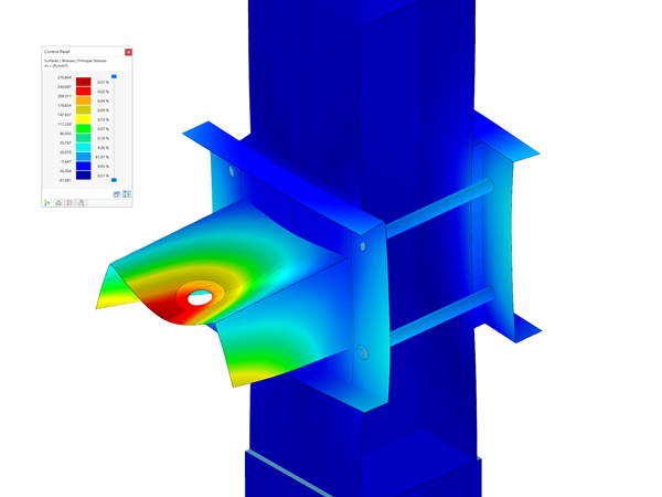
The Steel Joints add-on for RFEM allows you to analyze steel connections using an FE model. The FE model is generated automatically in the background and can be controlled via the simple and familiar input of components.
Price of First License
2,110.00 USD
RFEM 6 | Additional Analysis

The Torsional Warping (7 DOF) add-on allows you to consider cross-section warping as an additional degree of freedom.
Price of First License
1,480.00 USD
RFEM 6 | Additional Analysis

The Nonlinear Material Behavior add-on allows you to consider material nonlinearities in RFEM for example, isotropic plastic, orthotropic plastic, isotropic damage).
Price of First License
1,480.00 USD
RFEM 6 | Additional Analysis
The Structure Stability add-on performs stability analysis of structures. It determines critical load factors and the corresponding stability modes.
Price of First License
1,300.00 USD
RFEM 6 | Additional Analysis
The Time-Dependent Analysis (TDA) add-on allows you to consider the time-dependent material behavior of members. The long-term effects, such as creep, shrinkage, and aging, can influence the distribution of internal forces, depending on the structure.
Price of First License
1,030.00 USD
RFEM 6 | Additional Analysis
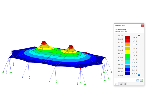
The Form-Finding add-on finds the optimal shape of members subjected to axial forces and tension-loaded surface models. The shape is determined by the equilibrium between the member axial force or the membrane stress and the existing boundary conditions.
Price of First License
2,060.00 USD
RFEM 6 | Design
The Stress-Strain Analysis add-on performs general stress analysis by calculating the existing stresses and comparing them with the limit stresses.
Price of First License
1,210.00 USD
RSTAB 9 | Main Program RSTAB 9

The modern 3D structural analysis and design program is suitable for the structural and dynamic analysis of beam structures as well as the design of concrete, steel, timber, and other materials.
Price of First License
2,910.00 USD
RSTAB 9 | Design
The Steel Design add-on performs the ultimate and serviceability limit state design checks of steel members according to various standards.
Price of First License
2,550.00 USD
RSTAB 9 | Additional Analysis
The Structure Stability add-on performs the stability analysis of structures. It determines critical load factors and the corresponding stability modes.
Price of First License
1,300.00 USD
RSTAB 9 | Design
The Stress-Strain Analysis add-on performs a general stress analysis by calculating the existing stresses and comparing them to the limit stresses.
Price of First License
1,120.00 USD
RSTAB 9 | Additional Analysis
The Torsional Warping (7 DOF) add-on allows for considering cross-section warping as an additional degree of freedom when calculating members.
Price of First License
1,480.00 USD
RSTAB 9 | Dynamic Analysis
The Modal Analysis add-on allows for the calculation of eigenvalues, natural frequencies, and natural periods for member, surface, and solid models.
Price of First License
1,210.00 USD
RSTAB 9 | Dynamic Analysis
Earthquakes may have a significant impact on the deformation behavior of buildings. A pushover analysis allows you to analyze the deformation behavior of buildings and compare them with seismic actions. Using the Pushover Analysis add-on, you can analyze the seismic actions on a particular building, and thus assess whether the building can withstand the earthquake.
Price of First License
1,300.00 USD
RFEM 6 | Design
The Timber Design add-on performs the ultimate, serviceability, and fire resistance limit state design checks of timber members according to various standards.
Price of First License
1,930.00 USD
RSTAB 9 | Design
The Timber Design add-on performs the ultimate, serviceability, and fire resistance limit state design checks of timber members according to various standards.
Price of First License
1,930.00 USD
RX-TIMBER 2 | Timber Structures

Timber design of single-span and wide-span glulam beams according to Eurocode 5 or DIN 1052
Price of First License
1,120.00 USD
RX-TIMBER 2 | Timber Structures

Timber design of simple, continuous, and Gerber beams with or without cantilever according to Eurocode 5 or DIN 1052
Price of First License
360.00 USD
RX-TIMBER 2 | Timber Structures

Timber design of rectangular and circular columns according to Eurocode 5 or DIN 1052
Price of First License
360.00 USD
RX-TIMBER 2 | Timber Structures

Timber design of coupled purlins and continuous beams according to Eurocode 5 or DIN 1052
Price of First License
360.00 USD
RX-TIMBER 2 | Timber Structures

Timber design of three-hinged frames with finger joint connections according to Eurocode 5 or DIN 1052
Price of First License
360.00 USD
RX-TIMBER 2 | Timber Structures

Timber design of stiffening truss bracing according to Eurocode 5 or DIN 1052
Price of First License
360.00 USD
RX-TIMBER 2 | Timber Structures

Timber design of flat, monopitch, and duopitch roofs according to Eurocode 5
Price of First License
360.00 USD
RSTAB 9 | Dynamic Analysis
The Response Spectrum Analysis add-on performs seismic analysis using the multi-modal response spectrum analysis. The spectra required for this can be created in compliance with the standards or can be user-defined. The equivalent static forces are generated from them. The add-on includes an extensive library of accelerograms from seismic zones that can be used to generate response spectra.
Price of First License
1,390.00 USD
RFEM 6 | Special Solutions

The two-part Optimization & Costs / CO2 Emission Estimation add-on finds suitable parameters for parameterized models and blocks via the artificial intelligence (AI) technique of particle swarm optimization (PSO) for compliance with common optimization criteria. Furthermore, this add-on estimates the model costs or CO2 emissions by specifying unit costs or emissions per material definition for the structural model.
Price of First License
1,480.00 USD
RFEM 6 | Special Solutions
The Multilayer Surfaces add-on allows you to define multilayer surface structures. The calculation can be carried out with or without the shear coupling.
Price of First License
1,300.00 USD
RFEM 6 | Design
The Aluminum Design add-on performs the ultimate and serviceability limit state design checks of aluminum members according to various standards.
Price of First License
1,750.00 USD