In RFEM 5 and RSTAB 8, you can check the deformations in the shear center by using the RF‑/FE‑LTB add-on module (see Image 02). The deformations that additionally result from the displacements or rotations can only be checked with a surface model in RFEM 5.
Deformations of Craneway
I am trying to manually check the deformations from the CRANEWAY add-on module. However, I obtain large deviations. How to explain the differences?
Answer:
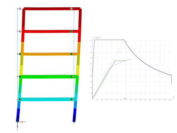
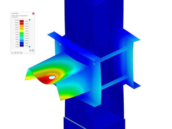
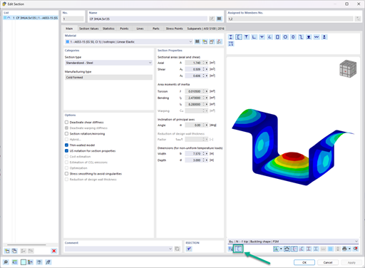
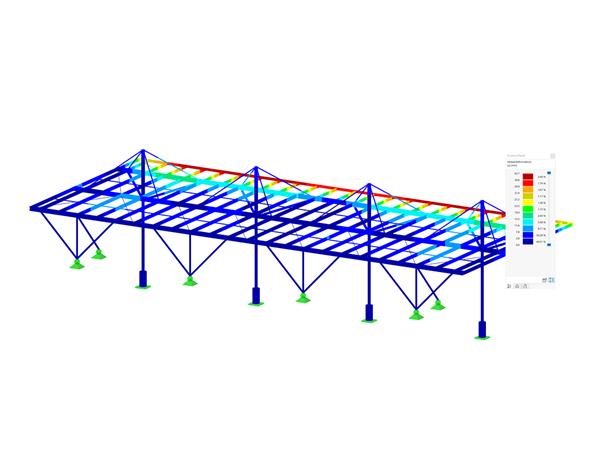
The internal forces and deformations are determined according to the second-order analysis for torsional buckling, taking into account 7 degrees of freedom. For a linear calculation of deformations, a vertical or horizontal load only results in one vertical or horizontal deformation. Since the internal forces refer to the deformed structure and there is a nonlinear analysis, this is not valid for the second-order torsional buckling analysis.In RFEM 5 and RSTAB 8, you can check the deformations in the shear center by using the RF‑/FE‑LTB add-on module (see Image 02). The deformations that additionally result from the displacements or rotations can only be checked with a surface model in RFEM 5.
Author
Mr. Rehm is responsible for developing products for timber structures, and he provides technical support for customers.
Downloads
Do you have any questions?
The three types of moment frames (Ordinary, Intermediate, Special) are available in the Steel Design add-on of RFEM 6. The seismic design result according to AISC 341-22 is categorized into two sections: member requirements and connection requirements.
The Steel Design add-on in RFEM 6 now offers the ability to perform seismic design according to AISC 341-16 and AISC 341-22. Five types of seismic force-resisting systems (SFRS) are currently available.
The three types of moment frames (Ordinary, Intermediate, Special) are available in the Steel Design add-on of RFEM 6. The seismic design result according to AISC 341-16 is categorized into two sections: member requirements and connection requirements.
Moment frame design according to AISC 341-16 is now possible in the Steel Design add-on of RFEM 6. The seismic design result is categorized into two sections: member requirements and connection requirements. This article covers the required strength of the connection. An example comparison of the results between RFEM and the AISC Seismic Design Manual [2] is presented.
In the ultimate configuration of the steel joint design, you have the option to modify the limit plastic strain for welds.
The "Base Plate" component allows you to design base plate connections with cast-in anchors. In this case, plates, welds, anchorages, and steel-concrete interaction are analyzed.
In the "Edit Section" dialog box, you can display the buckling shapes of the Finite Strip Method (FSM) as a 3D graphic.
- Design of five types of seismic force-resisting systems (SFRS) includes Special Moment Frame (SMF), Intermediate Moment Frame (IMF), Ordinary Moment Frame (OMF), Ordinary Concentrically Braced Frame (OCBF), and Special Concentrically Braced Frame (SCBF)
- Ductility check of the width-to thickness ratios for webs and flanges
- Calculation of the required strength and stiffness for stability bracing of beams
- Calculation of the maximum spacing for stability bracing of beams
- Calculation of the required strength at hinge locations for stability bracing of beams
- Calculation of the column required strength with the option to neglect all bending moments, shear, and torsion for overstrength limit state
- Design check of column and brace slenderness ratios
Recommended Products for You