Answer:
A critical load factor specifies which factor can be used to increase the load until the structural system fails. If it is smaller than one, the calculation according to the second-order analysis is usually unstable, as the structural system is already subjected to the critical load. This factor is also referred to in the standards. For example, Eurocode 3 specifies that the calculation according to the second-order analysis is no longer necessary as of the critical load factor of 10.The critical load factor can be determined using the RF‑STABILITY or RSBUCK add-on module.


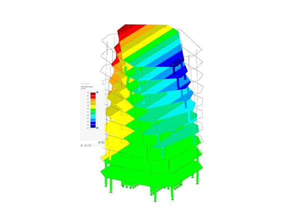


.png?mw=600&hash=49b6a289915d28aa461360f7308b092631b1446e)

