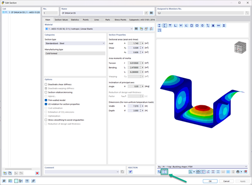
A member's boundary conditions decisively influence the elastic critical moment for lateral-torsional buckling Mcr. The program uses a planar model with four degrees of freedom for its determination. The corresponding coefficients kz and kw can be defined individually for standard-compliant cross-sections. This allows you to describe the degrees of freedom available at both member ends due to the support conditions.


.png?mw=600&hash=49b6a289915d28aa461360f7308b092631b1446e)