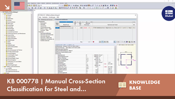
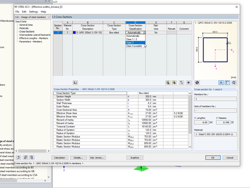
In the default setting, the cross-section class for each member and load case is determined automatically in the design modules. In the input window of the cross sections, however, the user can also specify the cross-section class manually, for example if local buckling is excluded by the design.


.png?mw=600&hash=49b6a289915d28aa461360f7308b092631b1446e)