Do you have any questions about Dlubal products or need assistance in selecting the right one for your project?
I'm here to help. You can easily reach me through the contact options provided below.
Looking forward to hearing from you!


Quick and Easy Generation of Loads

Snow Load Generator
The snow load generator can generate snow loads as member loads or surface loads.
Additional snow loads such as drifted snow loads, snow overhangs, and snow guards can be taken into account as well.
The following standards are available:
-
 EN 1991-1-3 (incl. National Annexes)
 -
 DIN 1055-5
 -
 CTE DB-SE-AE
 -
 ASCE/SEI 7-16

Wind load generator
Wind loads can be automatically generated as member loads or area loads on the following structural components (optional with internal pressure for open buildings):
- Vertical walls
- Flat roofs
- Monopitch roofs
- Duopitch/troughed roofs
- Vertical walls with roof
The following standards are available:
-
EN 1991-1-3 (incl. National Annexes)
-
DIN 1055-4
-
CTE DB-SE-AE
-
ASCE/SEI 7-16

Generating Member/Line Loads from Surface Loads
Area loads can be automatically converted into member or line loads. There are 3 options available for this:
- Generate Member Loads from Area Load via Plane
- Member loads from area loads via cells
- Line loads from surface loads on openings
In the case of member loads from area loads, a plane has to be defined via corner nodes or cells have to be selected in the graphic. The area load can either be applied to the entire surface or only the effective or projected surface of the members.
For the 'Line Loads from Area Loads on Openings' function, the corresponding openings are selected.
Online Manual RFEM | Member Loads from Area Loads via Plane
Generating Member Loads from Free Line Load
For pure member models such as grillages, you can define free line loads (e.g. from conveyor belts) and transfer them proportionally to members.
More Information
Generating Member Loads from Coating
Coating loads can be generated as member loads from ice loads, claddings, and so on.
For this, you only have to specify the thickness and specific weight of the coating.
Manual RFEM 5
Generating Loads from Accelerated Motion
This generator creates loads as a result of an acceleration or rotation (e.g. from tower cranes), which acts on specific objects of the model.
The mass is determined from the self-weight.
More Information


.png?mw=350&hash=c6c25b135ffd26af9cd48d77813d2ba5853f936c)


![Reduction of Building to Cantilever Structure: The individual mass points represent the floors. The deflection due to the normal compression forces shown in (a) is (b) converted into equivalent moments of displacement or shear forces [2].](/en/webimage/009762/2420261/01-en-png-12-png.png?mw=350&hash=dd36dc43123116724231958668ad6cdcb13a0169)


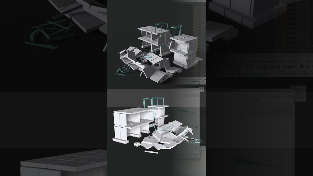
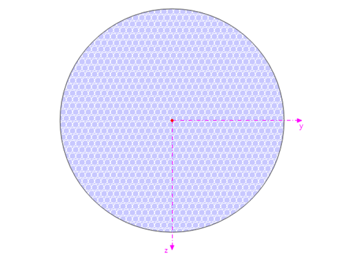
The results of solid stresses can be displayed as colored 3D points in the finite elements.
.png?mw=512&hash=ea9bf0ab53a4fb0da5c4ed81d32d53360ab2820c)
The number of degrees of freedom in a node is no longer a global calculation parameter in RFEM (6 degrees of freedom for each mesh node in 3D models, 7 degrees of freedom for the warping torsion analysis). Thus, each node is generally considered with a different number of degrees of freedom, which leads to a variable number of equations in the calculation.
This modification speeds up the calculation, especially for models where a significant reduction of the system could be achieved (for example, trusses and membrane structures).

Display extended strains of members, surfaces, and solids (for example, the important principal strains, equivalent total strains, and so on) in the Project Navigator - Results in RFEM as well as in Table 4.0.
For example, you can display governing plastic strains when performing the plastic design of connections with surface elements.
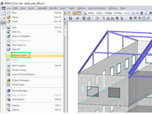
RFEM and RSTAB models can be saved as 3D glTF models (*.glb and *.glTF formats). View the models in 3D in detail with a 3D viewer from Google or Babylon. Take your VR glasses, such as Oculus, to "walk" through the structure.
You can integrate the 3D glTF models into your own websites using JavaScript according to these instructions (as on the Dlubal website Models to Download).
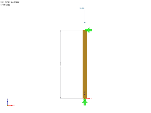
For example, can I define a member that absorbs all internal forces, except for the compressive axial forces?


.jpg?mw=350&hash=8f312d6c75a747d88bf9d0f5b1038595900b96c1)
