Prove that coupling different dimensional elements does not affect the results. A cantilever with a rectangular cross-section is fixed at one end and loaded at the other by concentrated forces. Neglecting its self-weight and assuming only small deformations, determine the cantilever's maximum deflections.

Do you have any questions?


Length: 00:00:06 min

Length: 00:00:34 min

Length: 00:03:54 min

Length: 00:00:59 min

Length: 00:00:16 min

Length: 01:05:29 min

Length: 00:02:38 min

Length: 00:55:56 min

Length: 01:08:12 min


.png?mw=350&hash=db8f562b3cbfea63fcdbce3b1237243a1ff807cf)


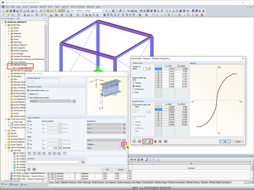
In RFEM 5 and RSTAB 8, it is possible to assign nonlinearities to member hinges. In addition to the nonlinearities "Fixed if" and "Partial activity", you can select "Diagram". If you select the "Diagram" option, you have to specify the according settings for the activity of the member hinge. For the individual definition points, it is necessary to specify the abscissa and ordinate values (deformations or rotations and the according internal forces) that define the hinge.

Designing rigid end plate connections is difficult for four-row connection geometries and multi-axis bending stresses, because there are no official design methods.

For structural dimensioning according to the valid rules, there are often several options or calculation methods to determine the internal forces. It is up to the engineer to decide which theory is suitable for designing the structure.
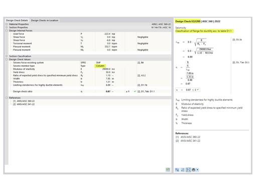
The three types of moment frames (Ordinary, Intermediate, Special) are available in the Steel Design add-on of RFEM 6. The seismic design result according to AISC 341-22 is categorized into two sections: member requirements and connection requirements.


In the ultimate configuration of the steel joint design, you have the option to modify the limit plastic strain for welds.

The "Base Plate" component allows you to design base plate connections with cast-in anchors. In this case, plates, welds, anchorages, and steel-concrete interaction are analyzed.
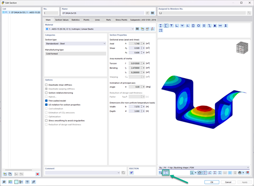
In the "Edit Section" dialog box, you can display the buckling shapes of the Finite Strip Method (FSM) as a 3D graphic.
- Design of five types of seismic force-resisting systems (SFRS) includes Special Moment Frame (SMF), Intermediate Moment Frame (IMF), Ordinary Moment Frame (OMF), Ordinary Concentrically Braced Frame (OCBF), and Special Concentrically Braced Frame (SCBF)
- Ductility check of the width-to thickness ratios for webs and flanges
- Calculation of the required strength and stiffness for stability bracing of beams
- Calculation of the maximum spacing for stability bracing of beams
- Calculation of the required strength at hinge locations for stability bracing of beams
- Calculation of the column required strength with the option to neglect all bending moments, shear, and torsion for overstrength limit state
- Design check of column and brace slenderness ratios
Are the models and presentations from Info Day 2018 freely available, and can you send them to me?
How can I additionally model welds for the connection of two surfaces with a contact solid?
Are the models and presentations from Info Day 2017 freely available, and can you send them to me?
How can I model a support of a member on a bracket with screws?
How can I incrementally increase loading?
Which analysis is used in RF‑STAGES or STAGES to calculate temporary loads and the generated combinations?

.jpg?mw=350&hash=91f398b559b26a6ac36fd7ecdf5e395e7b9b856d)


